3D printing skills
How to Design Simple 3D Printed Jigs
Updated June 11, 2026
Jigs are where a 3D printer stops making objects and starts making your other tools better. The design method is learnable in an afternoon: pick one reference surface, design the clamping before the geometry, and print stiff. Here it is, plus five jigs worth copying.
Some links on this page are affiliate links. If you buy through them, The Maker Guide may earn a small commission at no extra cost to you. We only point at product categories we would compare ourselves. Details.
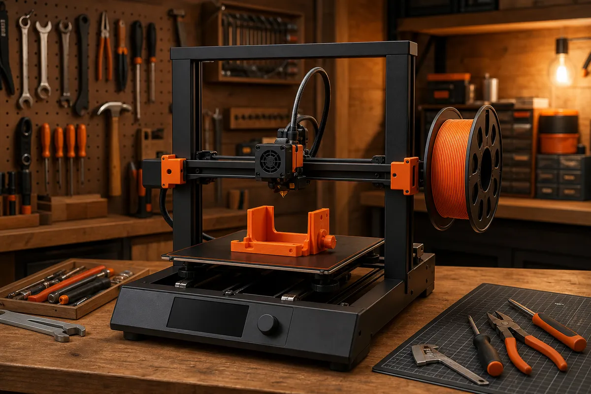
The method
- Name the operation. 'Drill a 5 mm hole, 20 mm from the edge, repeatedly' — a jig does one operation; multi-purpose jigs do several things badly.
- Pick one reference surface. Every accurate jig registers off a single face or edge of the workpiece. Two references fight each other the moment stock varies.
- Design the clamp first. How the work is held determines everything else. A jig you must hold by hand is a jig that drifts — design for a clamp, a fence, or your bench vise from the start.
- Add the guide. Drill bushings, saw slots, scribe edges, alignment pins. Make guides replaceable where they wear (a pressed-in metal bushing outlives printed holes 100:1).
- Print a fast draft, test on scrap, iterate. Two 40-minute drafts beat one 'final' four-hour print. The third version is usually the keeper — label it with engraved text: name, screw size, date.
Print settings for jigs (different from pretty prints)
- PLA, 4+ perimeters, 40%+ infill (or gyroid 25% with extra walls) — stiffness is the spec.
- Orient so the operation's force pushes layers together, not apart — a drill jig loaded across layer lines splits on schedule.
- 0.6 mm nozzle if you have one: jigs don't need fine detail, and double-speed printing changes how often you bother making them.
- Model holes 0.2 mm oversize and slots 0.3 mm over; test-fit pins and screws on a draft. Add heat-set inserts anywhere a screw will cycle more than a few times.
Five starter jigs that earn their filament
| Jig | What it does | The design lesson |
|---|---|---|
| Drill guide block | Square, repeatable holes at set offsets | Replaceable bushings; reference-edge thinking |
| Center finder | Scribes center lines on board edges and dowels | One-piece tools with zero moving parts |
| CNC corner stop | Bolts to the spoilboard grid; stock drops into a known XY zero | Design for your machine's workholding |
| Sanding blocks (radius + flat) | Consistent edge profiles on small parts | Ergonomics matter; sandpaper attachment is the hard part |
| Glue-up alignment cauls | Keeps panel glue-ups flat and registered | Printed parts + bolts + scrap wood = real fixtures |
When the printed jig isn't enough
Printed jigs top out where forces grow: heavy router work, metal drilling at production pace, anything that gets hot. The upgrade path is hybrid — printed locating geometry bolted to plywood or aluminum bone structure. You get plastic's free complexity and the substrate's stiffness.
And when a fixture needs to be flat-out machined — or you need fifty of a part the jig was for — a fab shop like OCreate can take the CAD you already made and run it in solid material. Designing the jig was the hard part; you've already done it.
Jig-making hardware kit
Drill bushing assortment (metric)
Pressed steel bushings make printed drill jigs last for hundreds of holes instead of ten.
See options on Amazon →M3/M4 heat-set inserts + screws
Any jig with adjustment or clamping wants metal threads from day one.
See options on Amazon →Toggle clamps, small
The fastest way to give a printed fixture real, repeatable clamping force.
See options on Amazon →Frequently asked questions
What's the best filament for jigs?
PLA, almost always — its stiffness is exactly what positioning accuracy needs, and shop-interior temperatures don't threaten it. Move to PETG only if the jig takes impacts or lives somewhere warm, and accept the small accuracy cost of its flex.
How accurate can a 3D printed jig be?
A calibrated printer holds ±0.1–0.2 mm over jig-sized parts, and a reference-edge design hides most of that. The jig's repeatability — same result every time — is typically better than its absolute accuracy, which is exactly what repetitive operations need.
Where do I find jig designs to start from?
Search Printables and similar libraries for 'drill guide,' 'center finder,' or your tool's model number — then learn parametric basics (Fusion 360, FreeCAD, OpenSCAD) early. Jigs are dimension-specific by nature; editing someone's parametric model is the actual workflow.